Podcasting since 2005! Listen to Latest SolderSmoke

Monday, March 18, 2024

Listen to me talking to Jean Shepherd in 1976. I was 18 years-old.


Wow, here is a blast from the past.  I recently read a good article about Shepherd by A. David Wunsch in the Spring 2022 issue of the AWA Journal. David correctly focused on Shep's obsession with the Heising modulator, and the very negative impact ("Your mother should take you to a doctor!") that this had on his dating life. 

I was telling my wife about this article, and I commented that I had once spoken to Shep during an early morning call-in show on WMCA New York.  I told her that someone had sent me a recording of this brief conversation. 

The call took place in 1976.  Shep was appaearing as a guest on the late-night radio show of Long John Nebel and Candy Jones.   I was 18 years old. My callsign was WB2QHL.  The recording was sent to me by Matt KC8COM in 2006. Thanks Matt!  In 2008 I played the recording during SolderSmoke Podcast #90.  But I think this call merits a post on the SoldedSmoke blog, so here it is.  You can jump forward to about 3 minutes, 49 seconds.   

http://soldersmoke.com/JeanShepherd1976WMCA.mp3

One side note.  I told my wife that some time after the broadcast, I was once again up early in the morning, kind of absent-mindedly getting ready for work when I heard Shepherd talking on WMCA to some guy about ham radio.  It took me a moment to realize that this was a re-run, and that that guy was me!  

When I first listened to this I didn't realize that later in the recording (around 9:30) another fellow calls in an asks Shep about why he uses CW.  Shep is kind of short with him and ends up advising him to "go back to CB." I should note that in my conversation with Shep earlier in the program,  I told him that I was usually on "40 sideband."  He was nice to me, but said that he was mostly on 20 CW. 


Here is a good Wikipedia article on Long John Nebel: https://en.wikipedia.org/wiki/Long_John_Nebel

And here's one on his wife and WMCA co-host Candy Jones: 

Friday, March 15, 2024

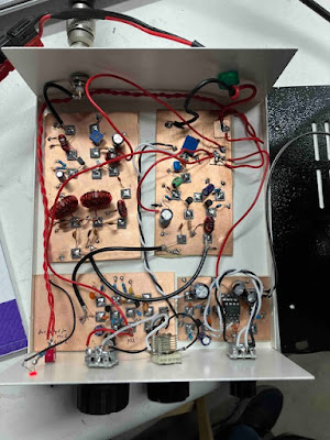
Finishing up (?) Version 2 of my 15-10 Transceiver (Video) -- An Annoying Residual Carrier Problem


Front panel is on. RF PA is installed. Balanced Modulator problem fixed (?) Rig is on the air with about 3 watts, working lots of DX.

But there is an annoying amount of carrier that is still getting through. It is only about .5 watts with sidebands of 100 watts PEP, but it annoys me, and it makes the setting of the carrier frequency in relation to the filter passband very critical: If I set the carrier a bit too far from the passband I get improved carrier rejection (from the filter), but I also lose the lows in both received and transmitted signals -- the RX just doesn't sound as good. I see it in both of the 15-10 rigs (IF of 25 MHz). There is less of it in the 17-12 meter rig (IF of 21.4 MHZ), and none of it in the Mythbuster (75-20 meters) (IF of 5.2 MHz). I am now wondering if this might be a consequence of my using a very high (25 MHz) single conversion IF in the 15-10 rigs. What do you folks think?

From my log: March 7, 2024 PUT VERSION 2 of the 15-10 RIG ON THE AIR! 10S 1528 OK2RZ Jiri – said I was 57! 15S 1539 S52WW 58 Damian. 15S 1602 SP1NQH Stev said I am big signal! 10S S58N 1726Z 10S S58N 1726Z 10S S57S 1728Z 10S IK4GRO Lauro 1735Z 10S W0CJV 1825Z Ft. Collins Gary 10s 2000Zish KK7TV Gary in Randy. Asked what software/microcontroller I was using. 10S KJ5MFF 2015Zish a middle school in New Mexico. KI5MFF control op sent picture


Thursday, March 14, 2024

"The New Essential Guide to Electronics in Shenzhen" A Book Review by Jenny List (with a video from Shenzhen)


This new book looks really good.  Great electronics info, with lots of cultural and linguistic wisdom. 

https://hackaday.com/2024/03/13/review-the-new-essential-guide-to-electronics-in-shenzhen/#more-668397 

Jenny's review brought to mind an older SolderSmoke blog post about Shenzhen. In this 2012 video  Bunnie Huang in Singapore talks about getting parts in that city: https://soldersmoke.blogspot.com/2012/08/singapore-knack.html

Thanks to Jenny, Naomi, and Bunnie.  

Wednesday, March 13, 2024

Using the RF Power Amplifier of the BITX40 Module


PA shematic from the BITX 40 Module
Click on the diagram for a better view

C.F. Rockey W9SCH (who alerted us in SPRAT 22 to the chicken sacrifice option) spoke of transistors that exhibit "quantum mechanical necromancy."  Rockey explained that when this happens, "The transistor simply turns up its toes and dies. Not even an Atomic Physicist can tell you why!"  

This often (very often!) happens with homebrew power amplifiers.  So when we find a good one, many of us stick with it, using the same power amp circuit in rig after rig.  I have done this with the power amplifier from the BITX40 Module. 

Mythbuster (75 & 20 Meter) version (early)  
Click on image for a better view. 
https://soldersmoke.blogspot.com/2021/08/mythbuster-video-13-rf-power-amplifier.html

Same amplifier built into Version 2 of the 15-10 Transceiver 
Click on image for a better view. 

In the build for the 15-10 transceiver you can see some changes.  I used an RD06HHF1 instead of an IRF-510.  I used an 8.1 volt zener diode instead of the regulator chip. I set the bias at around 5.5 volts DC on the gate of the RD06.   I used a smaller, metal can driver transistor (it works fine). I changed the input/output physical configuration between the pre-driver and the driver stages (I think it was kind of goofy the way I had it in the Mythbuster).  Finally, you can see how I used a small piece of copper tape (with conductive adhesive) to shield the line going from the driver transformer to the gate of the RD06.  The wire was too small to use a bit of shielded coax, but I think the copper tape and the copper clad board beneath it work just as well. 

Farhan provided me with some fascinating background on this circuit: 

Bill,

I just saw your post on the bitx40 power amp. The credit must go to Wes for this, it is from the Lichen transceiver described in 6.9 of the EMRFD. I merely copied it with some modifications for it to work with junkbox components.

It bears mentioning that at that time I didn't have a way of generating two tone signal or measuring the IMDR. Those came later when I built my own spectrum analyzer based on Wes and Terry White's spectrum analyzer. It was sheer luck that I picked this power chain that already had careful gain distribution.

For the output, the original build used and LPF with inductors wound on a ballpen shell and TV baluns cores instead of toroids. Again, it was incredibly lucky that they worked at all. 

- f

Tuesday, March 12, 2024

Justin's Receiver -- A 40 meter Superhet from AC8LV

 
FB Justin!  I really like the board that you are using as a base for the project.  And you have some great mentors in Nick and Loren.  

It is wonderful that you have that receiver working.  But I would tweak and peak quite a bit before taking on the transmitter.  Get a decent outside antenna -- even a dipole or a 1/4 wave with counterpoise would be a big improvment.  Like this one:  


And try to square away the grounding on the board (maybe some copper tape from Amazon) and the power supply you are using (I hope it is not one of those noisy wall warts).  When  you are experimenting, it can be useful to power varous stages with 9V batteries -- this is a good way to find out where noise is coming from.  If your AF amp is squealing at 12 volts, you need to break the feedback loop that is leading to oscillation.  Often the feedback is through the power supply.  Finally, try to get that homewbrew crystal filter working -- if the bandpass is uneven, you just need some impedance matching at the input and output.  

Great work Justin!   Keep at it.  73  Bill 

Bill,

I am sending video and pictures of my 40m  superhet that I built. I have it on the floor in an extra room in the house. The antenna is a stock vhf dipole that came with my rtl sdr which I use as a spectrum analyzer. In one of the clips I am receiving RW7K. I have been working on the station for the past year with help from Loren Moline, WA7SKT through texts when I have a problem. The LO / VFO is from Nick Woods Videos.

Next, I will build an outdoor antenna and the transmitter section. I first started homebrewing at the beginning of the pandemic, but this is by far my largest accomplishment. I would like to thank you and Pete for the soldersmoke videos which have been a great inspiration.

I will send more updates when the transmitter section is finish along with a much longer description of the projects

Thank you

Justin Elliott
AC8LZ

Bill, Pete, and Dean 


Thank you for the compliment. Pete, I want you to know, I’m a huge fan and I enjoy the one-liner jokes. I enjoy your contributions to the videos when you’re on Dean. 

Here are pics / videos of my superhet. 

The bandpass filter is a homebrew version of qrp labs design for 40m, I had to add an extra capacitor to get the bandpass where I wanted it. It is 6.9mhz to 7.32mhz. 

Mixer / demods are ade-ask.

The rf amps are kits i bought online, assembled, then used the schematics to replicate. They are the W7OI created and which have been mentioned on the channel

The LO/VFO are arduino driven from Nick Woods (M0NTV) YouTube channel. I believe episode 26

The crystal filter was built for 9MHz, but when I swept it I found the bandpass was saw toothed, so I used a commercial filter that Loren Moline WA7SKT sent. 

The audio amplifiers are a Common Emitter Amp I found on YouTube, I can’t recall the channel and a commercial amplifier, which I can now reproduce as I have the schematics. 

The speaker is a 2W 8 ohm speaker. 

...

Justin Elliott
AC8LZ

Monday, March 11, 2024

Radio Items Picked-up at VWS Winterfest 2024 Hamfest

As always, click on image for a better view

Above you can see what I picked up at the Vienna Wireless Society's 2024 Winterfest Hamfest. 

-- On the left in the blue box is an MXM Industries SuperRX/TX 40 transceiver. It is a kit from a Texas company.   Superhet receiver with IF at 455 kHz.  Crystal controlled CW transmitter on 7040 kHz.  The oscillator works, but so far no receive signals.  I will have to troubleshoot.  Does anyone have a schematic? 

-- Behind the MXM there is a nice box marked "Diode Detector" I opened it up and there is just a solid state diode and a 50 ohm resistor to ground.   Box may be useful. 

-- I got a couple of books: "Weekend Projects" 1979 from ARRL, and "A History of QST -- Volume 1 Amateur Radio Technology 1915 - 2013" 2013 from ARRL. 

-- On top of the Weekend Projects book you see a "Crystal Holder" from Gross Radio of New York City.  W1UJR has some good history on this company:  https://w1ujr.com/written-word/gross-radio-company-circa-1931/  This device seem to be intended to hold in place a raw piece of quartz!  Cool. 

-- To the right of the books there is a serious-looking VFO.  One dollar!  Deal!  It is a CB VFO, but the markings say it puts out 5.44 to 5.99 MHz.  So it should be useful.  The dual speed dial is very nice.  

-- Above the VFO is a nice step attenuator from the "Arrow Antenna" company of Loveland Colorado. 

-- Further to the right are some Electric Radio and Antique Wireless Association magazines that Armand WA1UQO gave me.  Really nice.  The AWA mags have a very thoughtful piece (warts and all) on Jean Shepherd.  And the ER pile has an article by Scott WA9WFA that mentions my work on the Mate for the Mighty Midget receiver.  Thanks again Armand! 

-- I also got some ADE6+ surface mount mixers.  The price was right! 

Thanks to VWS for putting on this great hamfest! 

Thursday, March 7, 2024

The Wizard of Schenectady -- Charles Proteus Steinmetz

Such a beautiful article.   Ramakrishnan VU2JXN sent it to me.  It reminded me of how puzzeled we were when we found "Schenectady" on old shortwave receiver dials, amidst truly exotic locations.  Rangoon!  Peking!  Cape Town!  Schenectady?   Obviously this was due to General Electric's location in that New York State city.  But reading this article, I am thinking that the presence of Charles Proteus Steinmetz had something to do with it. His informal title (The Wizard of Schenectady)  confirmed that we have been right in awarding similar titles to impressive homebrewers. 

Here is the Smithsonian article that Ramakrishnan sent. 

https://www.smithsonianmag.com/history/charles-proteus-steinmetz-the-wizard-of-schenectady-51912022/#ixzz2lRMjrfit

And here is a link to a PBS video on Steinmetz: 

https://www.pbs.org/video/wmht-specials-divine-discontent-charles-proteus-steinmetz/

Here is a SolderSmoke blog post about "Radio Schenectady":

https://soldersmoke.blogspot.com/2020/07/radio-schenectady.html


Wednesday, March 6, 2024

N6ASD Builds a Zinc-Oxide Negative Resistance Transmitter (and a Spark/Coherer rig)


I saw this video and post on Hackaday this morning:


I got the fellow's callsign from  his Morse CQ.  
It is N6ASD in San Francisco. 

Check this out from his QRZ page: https://www.qrz.com/db/N6ASD

My journey into the world of amateur radio began in a very primitive way. My first "rig" comprised of a spark-gap transmitter and a coherer based receiver. A coherer is a primitive radio signal detector that consists of iron filings placed between two electrodes. It was popular in the early days of wireless telegraphy.

Spark transmitter (using a car's ignition coil to generate high-voltage sparks):

Coherer based receiver (using a doorbell for the "decoherer" mechanism):

When I keyed the transmitter, a high voltage arc would appear at the spark-gap and this produced (noisy) radio waves. The signal would be received by the iron-filings coherer on the other side of the room. A coherer is (usually) a one-shot receiver. You have to physically hit it to shake the filings and bring the detector back to its original state. That's what the doorbell hammer did. It would hit the coherer every time it received a signal. It amazed me to no end. A spark created in one room of my house could make the hammer move in another room. Magic!

Soon after this project, I started experimenting with *slightly more refined* crystal detectors and crystal radio circuits. As most of you would know, these amazing radios don't require any batteries and work by harnessing energy from radio waves. I guess these simple experiments instilled a sense of awe and wonder regarding electromagnetic waves, and eventually, this brought me into the world of amateur radio in 2015.

My main HF rig is an old ICOM IC-735. The only modification on this is radio is that it uses LED backlights (instead of bulbs):

Icom IC 735

With space at a premium in San Francisco, the antenna that I have settled for is an inverted vee installed in my backyard (and it just barely fits). I made the mast by lashing together wooden planks. For this city dweller, it works FB:

I have recently gotten into CW, and it has definitely become my mode of choice.

I'm a self-taught electronics enthusiast and I love homebrewing radio circuits. I'll be sharing more info about them soon.

Thanks for checking out my page. I hope to meet you on the air!

73,
N6ASD


Tuesday, March 5, 2024

A Contact with my Old Azorean DSB Transceiver


I've been thinking about balanced modulators, and I wanted to see how some of my early circuits performed.  So I pulled this OLD Double Sideband rig off the shelf and fired it up. The balanced modulator -- and everything else! - worked fine,  and I soon made contact on 17 meter SSB with Gene, AB9GK. 

This was the first DSB transceiver that I ever built.  I made this out in the Azores, probably in 2000 or 2001.  Years later I had replaced the RF power amplifier with a "JBOT" (Just a Bunch of Transistors) designed by Farhan.  

Over on my YouTube channel a comment came in from my friend Jack:  

"Looking inside and seeing the o-scope probe in place while the radio was on the air reminded me of neurosurgery where the patient is awake and talking while the surgeon probes different brain regions soliciting feedback. Sure, ham radio isn't neurosurgery, but it's not too far at times. Also, you already have rocket science covered."


Here is an article about my build of that first rig:


I think the article captures well the trials and tribulations faced by new homebrewers, perhaps with the twist that comes from being out in the middle of the Atlantic ocean.  

Mike WU2D is having similar fun with his homebrew 10 meter DSB transceiver: 

I was struck by how similar Mike's early QSO experiences were with mine.  We both put our DSB transmitters on the air before they made their way into real cabinets or boxes. 

Here's mine from 2001 in the Azores: 


Sunday, February 25, 2024

Innovation and a Dual Band Sweep with Version 2 of the 15-10 Transceiver


Here are a couple of videos on Version 2 of my 15-10 SSB transceiver.  In the video above I try to show the advances and innovations that have been made since the start of my BITX construction adventure back in 2013.  

 The video below shows the receiver in action this morning on 15 and 10 meter SSB.  I think it sounds pretty good. 


Click on the image for a better look

Farhan asked what the passband of the 25 MHz crystal filter looked like.  I sent him this.  I think it looks very good, and shows that it is possible to use an IF this high.  This permits us to not only set up the transceiver for dual band coverage (in this case 15 and 10 meters), but it also allows for a lower frequency VFO (in this case around 3.5 MHz) with a resulting increase in VFO stability.  


Saturday, February 24, 2024

More on "Kludge" -- Merriam-Webster's Pronunciation Guide

 https://www.merriam-webster.com/dictionary/kludge

What say our British cousins?  How do you pronounce the word? 

Kluge as in huge? 

Kludge as in fudge? 


Innovations and Inventions in Garages and Basements

The Hewlett-Packard garage

There is a lot of inspirational stuff in this blog post, especially for those of us who work in home workshops, often in garages or basements. 


Thanks to HackaDay for alerting us to this. 

Designer: Douglas Bowman | Dimodifikasi oleh Abdul Munir Original Posting Rounders 3 Column